0069 00
TM 1-6625-724-13&P
0069 00-22
TASK 6 - BALANCE TAIL ROTOR
PROCEDURE 1: EQUIPMENT INSTALLATION
a.
Remove AVA tail rotor balancing equipment from transport case. Check for possible damaged equipment and
frayed cables.
b.
Install DAU in canvas carrying case.
c. Place DAU in right forward facing troop seat with connectors facing up and secure DAU using aircraft shoulder
and lap belts and canvas straps. If no troop seats are installed, the DAU may be secured to the D-rings found
on the aircraft cabin floor.
d. Connect power cable (29104700) to aircraft's 28 Vdc utility receptacle at station 293, right side, on cabin
ceiling and to DAU receptacle marked 28 Vdc.
e.
Locate CADU in aircraft. Connect CADU to DAU cable (29325601) to CADU and to DAU receptacle marked
CADU.
PROCEDURE 2: ACCELEROMETER INSTALLATION
a.
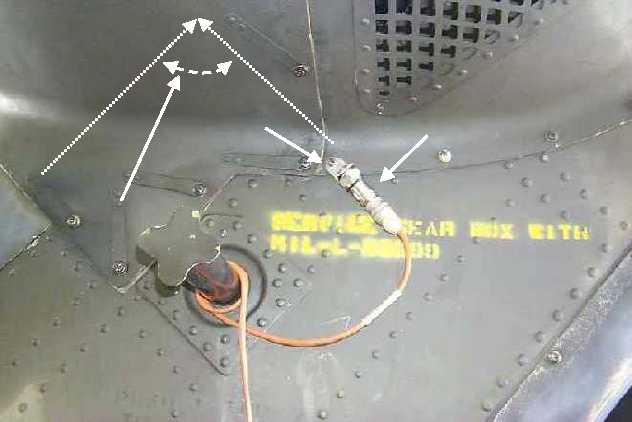
Remove screw from left side of pylon at bottom of tail gearbox aft fairing, see figure 13.
b.
Mount UH-60 accelerometer bracket (29313000) on pylon with pylon screw 90 degrees to leading edge of
pylon.
c.
Install accelerometer (28110900) on accelerometer bracket. Ensure connector is facing down and to the rear.
d.
Connect accelerometer cable (29105600) to accelerometer.
e.
Run cable down left side of pylon. Secure cable to extended steps on pylon and continue routing cable
through the tie-down ring located on right side of tail cone.
f.
Connect accelerometer cable to the DAU receptacle marked ACC4.
Figure 13. Tail Rotor Accelerometer Placement
Camloc
Tail Rotor
Drive Shaft
Accelerometer
Align accel so that it is
perpendicular to t/r
driveshaft


