TM 1-6625-724-13&P
0070 00
0070 00-5
TASK 1 - TEST EQUIPMENT INSTALLATION/CHECKOUT
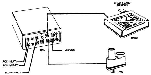
Figure 1. Typical AVA Test Setup Configuration
PROCEDURE 1: EQUIPMENT INSTALLATION
a. Remove AVA blade tracking equipment from transport case. Check for possible damaged equipment and
frayed cables. Figure 1 is the typical AVA test setup configuration.
b. Install DAU in canvas carrying case.
c. Place DAU behind the pilot's seat with the connectors facing up and secure DAU using canvas straps and
D-rings.
d. Remove hood assembly from one of the pilot's console lights. Remove the bulb. Plug AH-1S power cable
adapter (29317100), see figure 2 into lamp socket. Ensure that the lamp intensity is set to full intensity
(clockwise).
e. Connect grounding clip to a screw head or any non-painted metal surface, which will provide an adequate path
to aircraft ground.
f. Connect power cable (29104700) to the AH-1S power cable adapter (29317100) and to the DAU receptacle
marked 28 Vdc.
g. Place CADU in front seat. Connect CADU to DAU cable (29325601) to CADU and to DAU receptacle marked
CADU.
PROCEDURE 2: MAGNETIC RPM SENSOR INSTALLATION
NOTE
The lateral pitch-horn bolt should be installed with its
head to the front-right (toward the centerline of the
aircraft) and the nut at the left-rear (outboard).
a. Remove the cotter pin, nut, and washer from the left lateral pitch-horn bolt on the fixed swashplate.