TM 1-6625-724-13&P
0069 00
0069 00-33
TASK 8 – 100 HOUR ENGINE OUTPUT SHAFT AND OIL COOLER VIBRATION TESTING
The following procedures provide instructions for the balance testing and balancing of the engine output shafts and
vibration testing of the oil cooler for the UH-60 helicopters using the AVA equipment.
PROCEDURE 1: EQUIPMENT INSTALLATION
a.
Remove AVA vibration test equipment from transport case. Check for possible damaged equipment and
frayed cables.
b.
Install DAU in canvas carrying case.
c.
Place DAU on right troop seat with connectors facing up and secure DAU using aircraft shoulder and lap belts
and canvas strap D-rings. If no troop seats are installed, the DAU may be secured to the D-rings found on the
aircraft cabin floor.
d.
Connect power cable (29104700) to aircraft’s 28 Vdc utility receptacle at station 293, right side, on cabin
ceiling and to DAU receptacle marked 28 Vdc.
e.
Place CADU in aircraft. Connect CADU to DAU cable (29325601) to CADU and to DAU receptacle marked
CADU.
PROCEDURE 2: ACCELEROMETER INSTALLATION
a.
On each input module, remove one nut at rear and down from lifting ring. (Not required on aircraft modified
with accelerometer block installed). See figures 19 and 20.
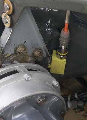
b. Install accelerometer (28110900) on accelerometer bracket, or block if installed. Mount accelerometer bracket
to input module with accelerometer vertical to input module (connector end facing up). Reinstall nut and
TORQUE TO 260 - 289 INCH-POUNDS. Do this for both modules.
c.
Connect accelerometer cables to accelerometers and route cables over top of input module, under cowl, under
forward edge of engine air inlet (if installed), through tiedown ring, and in window. Do this for both modules.
d.
Connect accelerometer cable from left input module (No. 1) to the DAU receptacle marked ACC1, and
accelerometer cable from right input module (No. 2) to the DAU receptacle marked ACC2.
Figure 19. No. 1 Input Module Accelerometer Installation (ACC1)