0069 00
TM 1-6625-724-13&P
0069 00-34
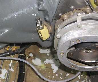
Figure 20. No. 2 Input Module Accelerometer Installation (ACC2)
e.
If the oil cooler vibration levels are to be tested, perform the following:
1.
Open oil cooler access doors.
2.
Wash axial fan with water if dirt is evident in the fan inlet flange area.
NOTE
Make sure that accelerometers and connectors do not
rest against any hoses.
3.
Install accelerometers in bracket (P/N 70361-03016-101) on oil cooler fan housing. Install vertical
accelerometer with connector end facing up and fore-aft accelerometer with connector end facing forward.
See figure 21.
4.
Attach accelerometer cables to the accelerometers. With masking tape, label the cabin end of each cable
as follows:
a.
Vertical accelerometer on accelerometer bracket, label 3.
b.
Fore-aft (F/A) accelerometer on accelerometer bracket, label 4.
NOTE
Make sure the cables have adequate clearance from any
moving or hot parts.
5.
Route the accelerometer cables through the oil cooler compartment and into the cabin. Secure the cables
tightly at several places in the oil cooler compartment with tiedown straps, item 368, Appendix D, of
Technical Manual TM 1-1520-237-23.
6.
In the cabin, connect accelerometer cables as follows (refer to figure 2):
a.
Connect accelerometer (3) cable labeled 3 to the DAU receptacle marked ACC3.
b.
Connect accelerometer (4) cable labeled 4 to the DAU receptacle marked ACC4.