TM 1-1520-265-23
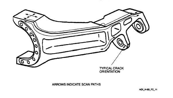
Figure 2-11. Spindle Horn
2.11.3.7 Marking and Recording of Inspection Results. Mark and record inspection results as required by paragraph 1.3.
2.11.4 Backup Method. Fluorescent Penetrant, refer to paragraph 1.4.7.
2.11.5 System Securing. The spindle horn, if removed, requires installation in accordance with the applicable technical
manuals listed in Table 1-1.
2.12 DROOP STOP CAM (ET).
2.12.1 Description (Figure 2-1. Index No. 1). The droop stop cam is the contact point between the main rotor spindle
and main rotor hubs which limit the droop of the blades when the rotor head is slowing or stopped.
2.12.2 Defects. This inspection is used to verify crack indications found visually on the droop stop cam. No cracks are
allowed.
2.12.3 Primary Method. Eddy Current.
2.12.3.1 NDI Equipment and Materials. (Refer to Appendix B.)
a.
Eddy Current Inspection Unit
b.
Probe, straight, shielded surface, 100 KHz-500 KHz
c.
Probe, right angle, shielded surface, 100 KHz-500 KHz, 90° 1/2 inch drop
d.
Cable Assembly
2-23