0073 00
TM 1-6625-724-13&P
0073 00-8
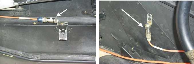
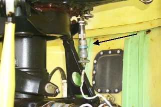
c. Rotate main rotor blades until the BLUE blade is forward, this should position the interrupter over the RPM
sensor. If any other blade is forward at this time, the interrupter requires repositioning.
d. Adjust sensor in bracket to obtain a gap of 0.025 between sensor and interrupter. Secure sensor with jam nuts
and install lockwire to hold jam nuts securely in place.
Figure 3. Magnetic RPM Sensor Installation
PROCEDURE 3: FORE/AFT AND VERTICAL ACCELEROMETER INSTALLATION
a. Install one accelerometer (28110900) on accelerometer mounting bracket (29313000). Mount accelerometer
bracket to the right side of the pilot's seat pan (side next to the door). Ensure that the connector is facing aft.
This is the fore/aft accelerometer, see figure 4.
b. Install one accelerometer (28110900) on accelerometer mounting bracket (29313000). Mount accelerometer
bracket on the left side of the pedestal with panel screw. Ensure that the connector is facing down. This is the
vertical accelerometer, see figure 4.
c. Connect accelerometer cable (29105605) to fore/aft accelerometer and to the DAU receptacle marked ACC1.
d. Connect accelerometer cable (29105600) to vertical accelerometer and to the DAU receptacle marked ACC2.
Figure 4. Main Rotor Accelerometer Installation
PROCEDURE 4: TRACKER INSTALLATION
a. Secure UTD bracket (29328000) to chin of aircraft just above search light, figure 5, with screws long enough to
pass through the mating fastener and extend a minimum of two threads.
NOTE
If the UTD captive mounting bolts are lost or damaged,
use NAS1305-14 bolts as replacements.
F/A Accel
Vertical Accel
Magnetic RPM
Sensor