TM 1-6625-724-13&P
0071 00
0071 00-9
TASK 1 – TEST EQUIPMENT INSTALLATION/CHECKOUT
NOTE
If magnetic sensor is operational through SPU interface it
is not necessary to disconnect the aircraft wiring and
interface may be used without externally wiring this sensor.
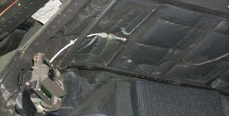
e. Disconnect the existing cable from the magnetic rpm sensor, and secure cable with a tie wrap to a convenient
location.
f.
Connect magnetic rpm sensor cable (29105403) to the magnetic rpm sensor. Route the cable along wire
bundle above R200 panel forward, and secure to cable with wire ties. Go across the front of the transmission
upper pylon and secure cable to wire bundle above L200. Route cable out of forward upper pylon ventilation
air intake panel out side the aircraft. Route cable down left side of the aircraft, securing to left upper hand hold
and into emergency air vent. Route cable under transparent barrier to DAU.
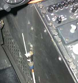
g. For AH-64D route cable outside the aircraft. Secure cable to existing handholds, and clamp as necessary.
Pass cable into forward cockpit through 5L90 access panel.
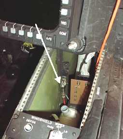
h. Connect magnetic rpm sensor cable to the DAU receptacle marked TACHO 1.
Figure 3. Lateral Accelerometer Installation (SPU/External Wiring)
Figure 4. Vertical Accelerometer Installation (External Wiring)
AH-64A
Vertical
Accelerometer
AH64D
Vertical
Accelerometer