TM 1-6625-724-13&P
0075 00
0075 00-9
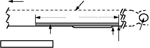
6 feet
Reflective Tape
Hub-end of Trim Tab
6 Inches Inboard of Trim Tab End
Blade Tip
Blade Leading Edge
DRAWING NOT TO SCALE
Hub
5017-005 A
6A. FORWARD ROTOR BLADES
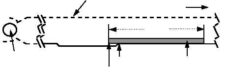
6 feet
Reflective Tape
Tip-end of Trim Tab
6 Inches Inboard of Trim Tab End
Blade Tip
Blade Leading Edge
Hub
DRAWING NOT TO SCALE
5017-006 A
6B. AFT ROTOR BLADES
Figure 6. Placement of Reflective Tape on Forward and Aft Rotor Blades
PROCEDURE 6: COMBINER TRANSMISSION OIL COOLING FAN SENSORS INSTALLATION
(50 HOUR CHECK ONLY)
a. Complete procedure 2.
b. Gain access to the combiner transmission cooling fan area, see figure 7.
c. Remove nuts from combiner transmission oil cooling fan mounting flange studs at the 5:00 and 8:30 clock
positions.
d. Mount an accelerometer mounting bracket (29339500) to each of the studs with the nuts provided. See figure
7.
NOTE
When mounting accelerometers, make certain that they
are in line with the corresponding axis (lateral and
longitudinal). See figure 7 top view.
e. Install accelerometer (28110900), accelerometer 1 (ACC1), in the lateral axis on the mounting bracket
(29339500) that is on the stud at 5 o’clock. The nose of the aircraft is at 12 o’clock position.
f. Install accelerometer (28110900), accelerometer 3 (ACC3), in the longitudinal axis on the mounting bracket that
is on the stud at the 8:30 clock position.
g. Connect 50-ft accelerometer cable assemblies (29105600) to the lateral accelerometer (ACC1), and to the
longitudinal accelerometer (ACC3).
h. Run the cable from the longitudinal accelerometer around the back of the oil cooler.
i. Identify each accelerometer cable (ACC1, and ACC3) and feed the cables through the lightening hole at station
482 on the right side.
j. Tie-wrap the accelerometer cables away from the sync shaft and engine drive shaft and route the cables to the
DAU.