TM 1-6625-724-13&P
0075 00
0075 00-11
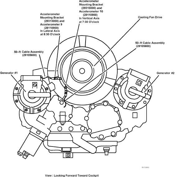
k. Tie-wrap the accelerometer cables clear of all rotating components and flight controls.
l. Connect AFT transmission lateral accelerometer (ACC9) cable to connector on the 15-ft. DAU cable assembly
(29085700) labeled ACC9.
m. Connect AFT transmission vertical accelerometer (ACC10) cable to connector on the 15-ft. DAU cable
assembly (29085700) labeled ACC10.
Figure 8. Aft Transmission Oil Cooling Fan Accelerometers Installation
PROCEDURE 8: AFTVIB CHECK SENSORS INSTALLATION (CROSS SHAFTS AND HANGER BEARINGS 4-7)
a. Complete procedure 2.
b. Not all sensors need to be installed, install only the accelerometers that are needed to diagnose the problem.
c. Gain access to the engine combining transmission area and hanger bearings Nos. 4, 5, 6 and 7.
d. Install an accelerometer (28110900), accelerometer 9 (ACC 9), on the accelerometer mounting pad on the C-
BOX No. 1 cross shaft input housing. See figure 9.
e. Install an accelerometer (28110900), accelerometer 10 (ACC 10) on the accelerometer mounting pad on the C-
BOX No. 2 cross shaft input housing. See figure 9.
f
Connect a 50-ft accelerometer cable assembly (29105600) to each accelerometer.


