TM 1-6625-724-13&P
0006 00
0006 00-5
4. Installing Accelerometers
The specific position and orientation of the accelerometers is critical to the proper operation of the AVA.
An accelerometer installed upside down or on the wrong axis will cause a 180° phase measurement
error, causing adjustments to be recommended for the wrong blade or mass balance position. Consult
the appropriate work package at the back of this manual for mounting details. It is essential that the
accelerometer be in the proper position and orientation for the system to operate property. Verify the
accelerometer is attached firmly to the mounting block or bracket.
5. Installing Cables
Refer to the appropriate work package for details on cable routing in specific aircraft. Work package 0060
00 provides detailed information on each of the cable assemblies. Cable assembly part numbers typically
end in "XX" during discussion. These last two digits represent the fact that cables can be ordered in
various lengths, but the functionality remains the same. Table 1 lists the five input signal types and their
uses. Aircraft specific cables are listed in the aircraft work packages.
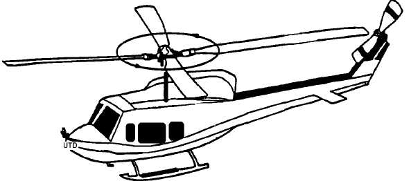
Figure 2. Universal Tracking Device (UTD) Mounting