0052 00
TM 1-6625-724-13&P
0052 00-2
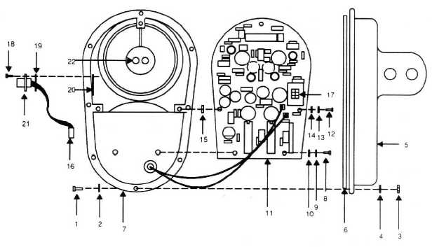
4. Remove three screws (12), three lock washers (13), three flat washers (14), and three nylon spacers (15)
from top section of PWA (11) allowing access to interior of top body (7).
5. Remove two diode caps (22) from two holes.
6. Disconnect cable connector P1 (16) from bottom side of the PWA (11) at J1 (17).
7. Remove four screws (18), gasket (19), and connector nut plate (20) allowing the cable assembly (21) to be
removed from the top body (7) for replacement.
b. INSTALLATION:
1. Apply thread-lock adhesive (item 1, WP0066 00) on threads of hardware.
2. Install diode caps (22) into two holes.
3. Install new cable assembly (21) into top body (7) with four screws (18), gasket (19), and connector nut
plate (20).
4. Connect cable connector P1 (16) to J1 (17) on bottom side of PWA (11).
5. Slowly position the PWA (11) aligning the two sensors on the bottom side of the PWA (11) into two holes
(22) in the top body (7).
6. Install three screws (12), three lock washers (13), three flat washers (14), and three nylon spacers (15).
7. Install two screws (8), two split lock washers (9), and two flat washers (10).
8. Verify O-ring (6) is in the base (5).
9. Apply silicone adhesive (item 2, WP0066 00) to mating surfaces of base (5) and body (7).
10. Install base using eight hex nuts (3), eight flat washers (4), eight screws (1), and eight flat washers (2).
Figure 1. UTD Cable Assembly Removal and Installation
END OF WORK PACKAGE


